
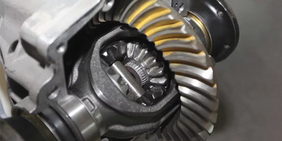
Gear Contact Test
Prepare crownwheel for examining tooth contact. After setting the correct backlash, the crownwheel and pinion tooth alignment should be checked for optimum contact. This may be achieved by applying a marking cream such as Prussian blue, red lead, chrome yellow, red or yellow ochre etc. to three evenly spaced groups of about six teeth round the crownwheel on both drive coast sides of the teeth profiles. Apply a load to the meshing gears by holding the crownwheel and allowing it to slip round while the pinion is turned a few revolutions in both directions to secure a good impression around the crownwheel. Examine the tooth contact pattern and compare it to the recommended impression.
Gear Structure
Understanding tooth contact marks (Fig. (a-f)) If the crown wheel to pinion tooth contact pattern is incorrect, there are two adjustments that can be made to change the position of tooth contact. These adjustments are of backlash and pinion depth.

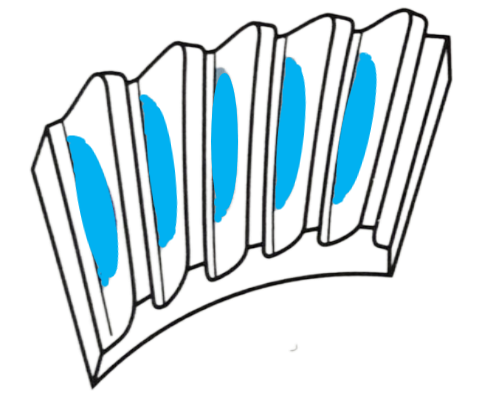
Gear Contact Patterns

Optimal Contact: pattern is concentrated in the center of the drive gear tooth.

HIGH CONTACT
LOW CONTACT

TOE CONTACT
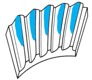
HEEL CONTACT
Final drive axle noise and defects
Incorrect meshing of crown wheel and pinion teeth
- Abnormal noises produced by poorly meshed teeth generate a very pronounced cyclic pitch whine in the speed range at which it occurs whilst the vehicle is operating on either drive or overrun conditions.
- Noise on drive If a harsh cyclic pitch noise is heard when the engine is driving the transmission it indicates that the pinion needs to be moved slightly out of mesh.
- Noise on overrun If a pronounced humming noise is heard when the vehicle’s transmission overruns the engine, this indicates that the pinion needs to be moved further into mesh.
- Slackness in the drive A pronounced time lag in taking the drive up accompanied by a knock when either accelerating or decelerating may be traced to end play in the pinion assembly due possibly to defective bearings or incorrectly set up bearing spacer and shim pack.
- Bearing noise Bearings which are defective produce a rough growling sound that is approximately constant in volume over a narrow speed range. Driving the vehicle on a smooth road and listening for rough transmission sounds is the best method of identifying bearing failure.
- A distinction between defective pinion bearings or differential cage bearings can be made by listening for any constant rough sound. A fast frequency growl indicates a failed pinion bearing, while a much slower repetition growl points to a defective differential bearing. The difference in sound is because the pinion revolves at about four times the speed of the differential assembly.
- To distinguish between differential bearing and half shaft bearing defects, drive the vehicle on a smooth road and turn the steering sharply right and left. If the half shaft bearings are at fault, the increased axle load imposed on the bearing will cause a rise in the noise level, conversely if there is no change in the abnormal rough sound the differential bearings should be suspect.